Quick Overview
In this article I’ll be covering Rust in Embedded Systems, more specifically GPIO(General Purpose Input Output) and PWM(Pulse Width Modulation) protocols. I’ll be talking about how to implement those in Rust, using Embassy and I’ll also be going through two different challenges that I had faced recently in a workshop.
Embassy-rs is short for Embassy Asynchronous Rust
Setup
We first need to define the entrypoint and bootloader so we’ll specify it like this:
use embassy_executor::Spawner;

#[embassy_executor::main]
async fn main(_spawner: Spawner) {
    let peripherals = embassy_rp::init(Default::default());
}
The init function takes care of all the peripheral initializations so that we don’t need to worry about all these.
We also have to specify:
#![no_main]
#![no_std]
That’s because Embassy-rs works in an asynchronous way and so we need to define main as async. Also because the microcontrollers that we are going to be using don’t run any framework/operating system we can’t rely on std.
Challenges
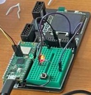
For those challenges I had a Pimoroni Pico Explorer Base, a Raspberry Pi Pico that I used to power up the board and a Pico Probe Debug for flashing.
First Task
Connect a green LED to GP4 and a red LED to GP5. Blink the LEDs consecutively, for 1 second each (i.e. when one LED is on, the other is off).
This one was fairly easy, we can just use GPIO(General Purpose Input Output) to program the LEDs after we set them up on the breadboard and connect the pins accordingly. First, let’s go through each part of the code:
#![no_main]
#![no_std]

use embassy_executor::Spawner;
use embassy_rp::gpio::{Level, Output};
use embassy_time::Timer;
use {defmt_rtt as _, panic_probe as _};
The first two lines were explained a little earlier, so there is no need to explain them again. Then, we import all the functions from the crates that we need.
Also, keep in mind that the last line is a must in your code and that it doesn’t run without it, as it handles the faults and detects both Rust panics, as well as HardFaults raised by the Cortex-M processor.
I’ll be explaining what each function does:
#[embassy_executor::main]
async fn main(_spawner: Spawner) {
    let peripherals = embassy_rp::init(Default::default()); // Defines the peripherals
    let mut pin_green = Output::new(peripherals.PIN_4, Level::Low); // Defines the green LED and sets it to low
    let mut pin_red = Output::new(peripherals.PIN_5, Level::Low); // Defines the red LED and sets it to low
    loop {
        pin_green.set_high(); // Turns on the green LED
        pin_red.set_low(); // Turns off the red LED
        Timer::after_secs(1).await; // Waits for 1 second
        pin_green.set_low();
        pin_red.set_high();
        Timer::after_secs(1).await;
    }
}
This is the main function. After we initialize the peripherals, we define each pin for the LEDs and the level at the beginning, meaning if it’s turned on or off at the start. The most important part consists in defining the output for each pin and then the loop is needed, because as explained earlier the MCU does not run any operating system so there is nothing to return. Afterwards, we set each pin to be turned on and off for one second each.

Second Task
Connect the RGB LED to GP0, GP1, and GP2. Write a program that increases the LED’s intensity with 10% each second.
For this task we are going to make use of PWM(Pulse Width Modulation) in order to program the LED’s intensity.
#![no_std]
#![no_main]

use embassy_executor::Spawner;
use embassy_time::Timer;
use embassy_rp::pwm::{Config as ConfigPwm, Pwm};
use {defmt_rtt as _, panic_probe as _};
We start off as usual, we import our crates and the panic handler.
#[embassy_executor::main]
async fn main(_spawner: Spawner) {
    let peripherals = embassy_rp::init(Default::default());
    let mut config: ConfigPwm = Default::default(); // Defining the PWM configuration

    config.top = 0x8000; // Defining the top value
    config.compare_a = 0x8000; // Defining the starting value
    config.compare_b = 0x8000;
Here, we define the peripherals, we intialize the defult PWM config, then we go ahead and also define the config.top and each of the compares for the duty cycle. In our case, 0x8000 is predefined value for our LED, so we also then specify the compare values for each of the pins. Think of it like this, the top value means the value for which the light is turned off and the compare value is the value for which the light is either on or off(e.g if it would be 0, it would be turned on at the maximum capacity).
    let mut pwm_green_red = Pwm::new_output_ab( // Defining the PWM on pin 0 and 1
        peripherals.PWM_SLICE0,
        peripherals.PIN_0,
        peripherals.PIN_1,
        config.clone()
        );

    let mut pin_blue = Pwm::new_output_a( // Defining the PWM on pin 2
    peripherals.PWM_SLICE1,
    peripherals.PIN_2,
    config.clone()
    );
In here, we initialize each of the pins for each led. I think the table below will be of help for this.
    loop {
            config.compare_a -= (config.top as f32 * 0.1) as u16;
            pwm_green_red.set_config(&config);

            config.compare_b -= (config.top as f32 * 0.1) as u16;
            pin_blue.set_config(&config);
            Timer::after_secs(1).await;
        }
}
The last part of the code, we just loop through, turning on each of the LEDs 10% more each second, by decreasing the maximum value(as explained earlier, they were turned off at the beginning).
